In modern electronics, reliable electrical connections are essential for efficient circuit performance. Wire To Board Connectors are widely used to link discrete wires directly to printed circuit boards (PCBs), providing a compact and secure interface. These connectors simplify assembly and maintenance while ensuring signal integrity.
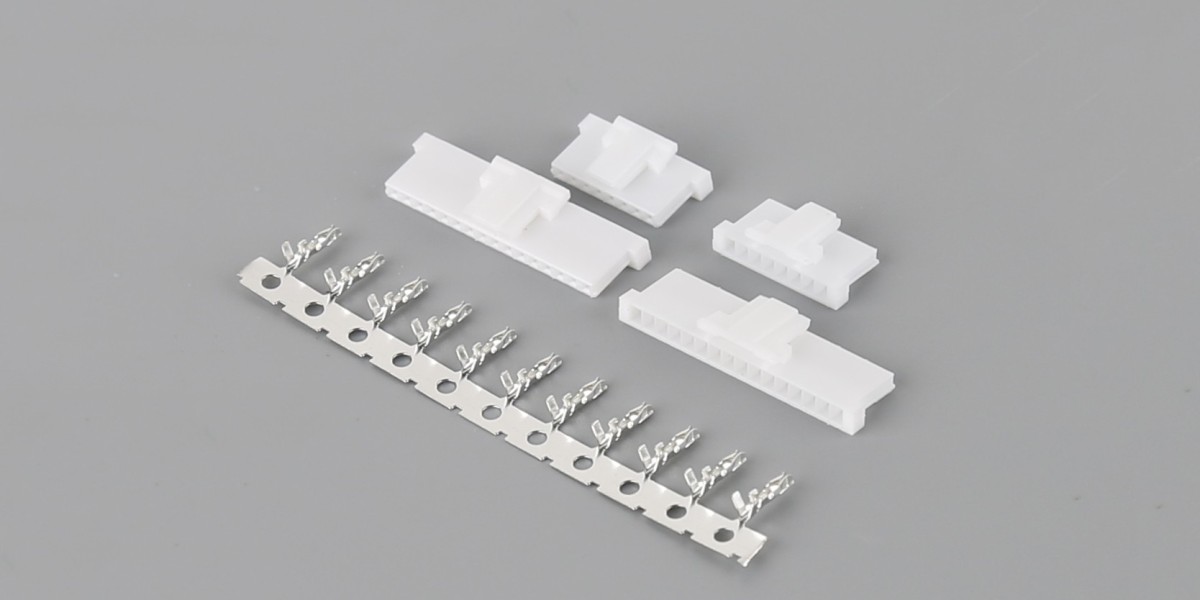
Wire To Board Crimp Style Connectors, in particular, offer a secure mechanical and electrical connection by crimping the wire to a terminal before mating it with the PCB housing. This method reduces the risk of loose connections, which is crucial in environments with vibration or thermal cycling. For example, a 24 AWG wire can typically handle currents up to 3A in standard crimp terminals, with insulation rated for 105°C.
Designers must consider factors such as pitch, current rating, and material. Common pitches for wire-to-board connectors include 2.54 mm, 3.96 mm, and 5.08 mm. Materials such as tin or gold-plated copper ensure low contact resistance, often less than 10 mΩ, which is critical for maintaining signal quality.
Moreover, these connectors are available in single-row or dual-row configurations, supporting anywhere from 2 to 40 circuits. This flexibility allows engineers to choose connectors suited for both low-power signal applications and higher-power distributions, making them versatile for consumer electronics, industrial controls, and automotive applications.
Wire To Board Crimp Style Connectors are especially valued for automated assembly processes, as the crimped terminals can be inserted quickly into the housing, reducing manual labor and improving production efficiency. Overall, understanding the technical characteristics and proper selection of wire-to-board connectors can enhance device reliability and streamline manufacturing processes.